Showing posts with label relay. Show all posts
Showing posts with label relay. Show all posts
Wednesday, October 9, 2013
Reducing Relay Power Consumption
Relays are often used as electrically controlled switches. Unlike transistors, their switch contacts are electrically isolated from the control input. On the other hand, the power dissipation in a relay coil may be unattractive for battery-operated applications. Adding an analogue switch lowers the dissipation, allowing the relay to operate at a lower voltage. The circuit diagram shows the principle. Power consumed by the relay coil equals V2/RCOIL. The circuit lowers this dissipation (after actuation) by applying less than the normal operating voltage of 5 V. Note that the voltage required to turn a relay on (pickup voltage)is usually greater than that to keep it on (dropout voltage).

In this respect the relay shown has specifications of 3.5 and 1.5V respectively, yet the circuit allows it to operate from an intermediate supply voltage of 2.5V. Table 1 compares the relay’s power dissipation with fixed operating voltages across it, and with the circuit shown here in place. The power savings are significant. When SW1 is closed, current flows through the relay coil, and C1 and C2 begin to charge. The relay remains inactive because the supply voltage is less than its pickup voltage. The RC time constants are such that C1 charges almost completely before the voltage across C2 reaches the logic threshold of the analogue switch inside the MAX4624 IC.

When C2 reaches that threshold, the on-chip switch connects C1 in series with the 2.5V supply and the relay coil. This action causes the relay to be turned on because its coil voltage is then raised to 5 V, i.e., twice the supply voltage. As C1 discharges through the coil, the coil voltage drops back to 2.5 V minus the drop across D1. However, the relay remains on because the resultant voltage is still above the dropout level (1.5 V). Component values for this circuit depend on the relay characteristics and the supply voltage. The value of R1, which protects the analogue switch from the initial current surge through C1, should be sufficiently small to allow C1 to charge rapidly, but large enough to prevent the surge current from exceeding the specified peak current for the analogue switch.
The switch’s peak current (U1) is 400mA, and the peak surge current is IPEAK = (VIN – VD1) / R1 + RON) where RON is the on-resistance of the analogue switch (typically 1.2 Ω). The value of C1 will depend on the relay characteristics and on the difference between VIN and the pickup voltage. Relays that need more turn-on time requires larger values for C1. The values for R2 and C2 are selected to allow C1 to charge almost completely before C2’s voltage reaches the logic threshold of the analogue switch. In this case, the time constant R2C2 is about seven times C1(R1 + RON). Larger time constants increase the delay between switch closure and relay activation. The switches in the MAX4624 are described as ‘guaranteed break before make’. The opposite function, ‘make-before break’ is available from the MAX4625. The full datasheets of these interesting ICs may be found at http://pdfserv.maxim-ic.com/arpdf/MAX4624-MAX4625.pdf
See More Detail[...]

In this respect the relay shown has specifications of 3.5 and 1.5V respectively, yet the circuit allows it to operate from an intermediate supply voltage of 2.5V. Table 1 compares the relay’s power dissipation with fixed operating voltages across it, and with the circuit shown here in place. The power savings are significant. When SW1 is closed, current flows through the relay coil, and C1 and C2 begin to charge. The relay remains inactive because the supply voltage is less than its pickup voltage. The RC time constants are such that C1 charges almost completely before the voltage across C2 reaches the logic threshold of the analogue switch inside the MAX4624 IC.

When C2 reaches that threshold, the on-chip switch connects C1 in series with the 2.5V supply and the relay coil. This action causes the relay to be turned on because its coil voltage is then raised to 5 V, i.e., twice the supply voltage. As C1 discharges through the coil, the coil voltage drops back to 2.5 V minus the drop across D1. However, the relay remains on because the resultant voltage is still above the dropout level (1.5 V). Component values for this circuit depend on the relay characteristics and the supply voltage. The value of R1, which protects the analogue switch from the initial current surge through C1, should be sufficiently small to allow C1 to charge rapidly, but large enough to prevent the surge current from exceeding the specified peak current for the analogue switch.
The switch’s peak current (U1) is 400mA, and the peak surge current is IPEAK = (VIN – VD1) / R1 + RON) where RON is the on-resistance of the analogue switch (typically 1.2 Ω). The value of C1 will depend on the relay characteristics and on the difference between VIN and the pickup voltage. Relays that need more turn-on time requires larger values for C1. The values for R2 and C2 are selected to allow C1 to charge almost completely before C2’s voltage reaches the logic threshold of the analogue switch. In this case, the time constant R2C2 is about seven times C1(R1 + RON). Larger time constants increase the delay between switch closure and relay activation. The switches in the MAX4624 are described as ‘guaranteed break before make’. The opposite function, ‘make-before break’ is available from the MAX4625. The full datasheets of these interesting ICs may be found at http://pdfserv.maxim-ic.com/arpdf/MAX4624-MAX4625.pdf

Saturday, August 31, 2013
Pulse Timer Control Relay Circuit with IC555
Today we would like to offers solutions for a set time for take control relay and take NO. / NC. contact to apply to control other devices . such as disable or enable the device.function of this circuit is using IC555 to determine the pulse and a resistor R1 to the period of time.
Pulse Timer Control Relay Circuit Diagram

R1 #Seconds
100k 2
220k 3
470k 6
1M 15
The increase provides more time to increase the value of the Capacitor.
Part List
R1 = 1 Meg, Preset Pot
R2 = 10K
R3,R4 = 1K
C1 = 10uF, 16V
C2 = 0.01uF
T1 = BC547 (Gen Purp NPN)
T2 = 2N2222 (Hi Current NPN)
D1 = 1N4001 (Gen Purp Si)
IC1 = 555 (Lo-Power version)
RLA1 = Relay, 9V (amps of your choice)
Pulse Timer Control Relay Circuit Diagram
R1 #Seconds
100k 2
220k 3
470k 6
1M 15
The increase provides more time to increase the value of the Capacitor.
Part List
R1 = 1 Meg, Preset Pot
R2 = 10K
R3,R4 = 1K
C1 = 10uF, 16V
C2 = 0.01uF
T1 = BC547 (Gen Purp NPN)
T2 = 2N2222 (Hi Current NPN)
D1 = 1N4001 (Gen Purp Si)
IC1 = 555 (Lo-Power version)
RLA1 = Relay, 9V (amps of your choice)
Friday, April 5, 2013
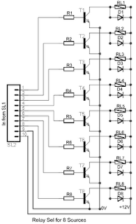
8 Relay Control Circuit
8 Relay Control Circuit
R1-8=4.7 Kohms T1-8= BD139 (R1-8=15 Kohms if T1-8=BD679)
RL1-8=6V-24V dc Relay D1-8=1N4148
See More Detail[...]
R1-8=4.7 Kohms T1-8= BD139 (R1-8=15 Kohms if T1-8=BD679)
RL1-8=6V-24V dc Relay D1-8=1N4148
Subscribe to:
Posts (Atom)