Thursday, May 30, 2013
Towbar Wiring Fitting Guides
Wiring Trailer Lights.
Wiring A Light Fitting.
Headlight Wiring 12 Volt Lights On A 24 Volt System Service.
Wiring A Switch With Light In Middle Of Circuit.
Light With Outlet 2 Way Switch Wiring Diagram.
Thread Wiring Clipsal Saturn Light Switches.
The Method I Used For Wiring The Lights For The.
How To Wire Two Lights Controlled From One Switch.
How To Towbar Wiring 12n 12s Fitting Guides.
Way Switch Wiring Diagram Variation 3 Electrical Online.
Sunday, May 26, 2013
Three sirens in one Circuit
This is a siren circuit diagram Here I have used UM3561 circuit diagram.This circuit can be operated with 3V.It can generate 3 sirens.Here I have used IC 2SC9013 you can use the same IC or similar IC. Use 8ohm 0.2W speaker.
 Note:-
* Dont use more than 3V
* Dont use this for unnecessary things
* Build this circuit on a PCB
See More Detail[...]
 Note:-
* Dont use more than 3V
* Dont use this for unnecessary things
* Build this circuit on a PCB
Monday, May 13, 2013
Live line Detector
Sunday, May 5, 2013
Nite Rider Lights
As a keen cyclist I am always looking for ways to be seen at night. I wanted something that was a novelty and would catch the motorists eye. So looking around at my fellow cyclists rear lights, I came up with the idea of NITE-RIDER. NINE extra bright LEDs running from left to right and right to left continuously. It could be constructed with red LEDs for use on the rear of the bike or white LEDs for an extra eye catcher on the front of the bike.All ICs are CMOS devices so that a 9V PP3 battery can be used, and the current drawn is very low so that it will last as long as possible.

Parts
1 555 timer IC4.
1 4027 flip flop IC1.
2 4017 Decade Counter IC2 and IC3.
3 4071 OR gate IC5, IC6 and IC7.
1 470 Ohm resistor 1/4 watt R3.
2 10K resistors 1/4 watt R1 and R2.
1 6.8UF Capasitor 16V C1.
9 Super brght LEDs 1 to 9.
1 9V PP3 Battery.
1 single pole switch SW1.
1 Box.
How The Circuit Works.
IC4, C1, R1 and R2 are used for the clock pulse which is fed to both the counters IC2 and IC3 Pin 14.
IC1 is a Flip Flop and is used as a switch to enable ether IC2 or IC3 at pin 13.
IC7a detects when ether IC2 or IC3 has reached Q9 of the counter pin 11.
IC5, IC6 and IC7a protects the outputs of the counters IC2 and IC3 using OR gates which is then fed to the Anodes of the
LEDs 1 to 9.
See More Detail[...]


Parts
1 555 timer IC4.
1 4027 flip flop IC1.
2 4017 Decade Counter IC2 and IC3.
3 4071 OR gate IC5, IC6 and IC7.
1 470 Ohm resistor 1/4 watt R3.
2 10K resistors 1/4 watt R1 and R2.
1 6.8UF Capasitor 16V C1.
9 Super brght LEDs 1 to 9.
1 9V PP3 Battery.
1 single pole switch SW1.
1 Box.
How The Circuit Works.
IC4, C1, R1 and R2 are used for the clock pulse which is fed to both the counters IC2 and IC3 Pin 14.
IC1 is a Flip Flop and is used as a switch to enable ether IC2 or IC3 at pin 13.
IC7a detects when ether IC2 or IC3 has reached Q9 of the counter pin 11.
IC5, IC6 and IC7a protects the outputs of the counters IC2 and IC3 using OR gates which is then fed to the Anodes of the
LEDs 1 to 9.
Wednesday, May 1, 2013
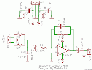
Simple Subwoofer Lowpass Filter using uA741 Single Op Amp Ic
This is the simplest Sub woofer Low Pass filter Circuit using uA741 single op amp ic. The circuit is very low cost with respect to their work. The cut off frequency of this circuit is 25Hz to 80Hz maximum. Using this circuit , you can easily design a 2.1 Sub-woofer Speaker System at your own Home. The circuit contains very few components.In Pakistan, the cost of this circuit with PCB is Rs:45 The same circuit is working in my own hand made sub-woofer system.
R1,R3,R4 = 10K 1/4W
R2=100K 1/4W
CY1,CY2 = 0.22uF Polyester
C1,C2 = 10uF/25V Electrolytic
IC1 = uA741A Single Op-Amp Ic + 8 Pin Ic Socket
3 Pin Male & Female Connector x 2
2 Pin Male & Female Connector x 1
PCB as in required size 4.5 cm x 3.4 cm
Subscribe to:
Comments (Atom)
