Showing posts with label simple. Show all posts

Saturday, January 11, 2014

Simple Power Switching Circuit Diagram

This Simple Power Switching Circuit Diagram provides on/off switching, soft starting, current monitoring, current tripping, and protection against over-current for a 30 Vdc power supply at normal load currents up to 2 A. The switch is turned on by an `on` command pulse; it is turned off by an `off` command pulse. An over-current trip can also be set on the bus side by a 6-digit binary signal, which is converted to an analog voltage and compared with the amplified voltage developed across a load-current-sensing resistor. 

Resistor/capacitor combinations (0.027 µ, 2 kfi) at the inputs of the current-sensing amplifiers act as low-pass filters: this introduces a few hundred /is of delay in the response to over-current, thereby providing some immunity to noise. The 0.022 µ capacitors connected to the drain terminals of the PFETs provide a Miller effect, which reduces the rate of change of the drain voltage and therefore the rate of rise of current at turn-on. The soft-turn-on time depends upon the load impedance and is typically 100 to 200 ms.

 Power Switching Circuit Diagram

Simple Power Switching Circuit Diagram

See More Detail[...]

Tuesday, December 24, 2013

Simple Solar Cell Voltage Regulator Circuit Diagram
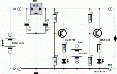
This is a Simple Solar Cell Voltage Regulator Circuit Diagram. This device is designed to be a simple, inexpensive ‘comparator’, intended for use in a solar cell power supply setup where a quick ‘too low’ or ‘just right’ voltage indicator is needed. The circuit consists only of one 5V regulator, two transistors, two LEDs, five resistors, two capacitors, and one small battery. Although a 4-V battery is indicated, 4.5 V (3 alkalines in series) or 3.6 V (3 NiCd cells in series) will also work. 

 Solar Cell Voltage Regulator Circuit Diagram

 Solar Cell Voltage Regulator Circuit Diagram

The specifications of voltage regulator IC1 are mainly determined by the size and number of the solar cells and the current pull of the equipment connected to the output. Here the low-drop 4805 is suggested but other regulators may work equally well as long as you observe the output voltage of the solar cells. Transistors T1 and T2 are complementary types i.e. one each of the pnp and npn variety. 

Although the ubiquitous BC557B (pnp) and BC547B (npn) are indicated, any small-signal equivalents out of the junk box will probably do. The values of voltage dividers R1/R6 and R3/R4 may need to be adjusted according to the type of transistor and its gain, or according to the desired voltage thresholds. Using the resistor values shown in the schematic, LED D2 turns on fully when the voltage is just above 5 volts. 

LED D1 turns on when the voltage drops below 4.2 volts or so. Between those two thresholds, there is a sort of no man’s land where both LEDs are on dimly. A buzzer or other warning device could be connected across the terminals of LED D1 to give a more substantial warning if the voltage drops below operating limits. The current consumption of the circuit is about 20 mA at 5 V, and it decreases with the voltage supplied by the solar cells.

See More Detail[...]

Tuesday, December 17, 2013

Simple Nicad Battery Charger

This simple charger uses a single transistor as a constant current source. The voltage across the pair of 1N4148 diodes biases the base of the BD140 medium power transistor. The base - emitter voltage of the transistor and the forward voltage drop across the diodes are relatively stable.  The charging current is approximately 15mA or 45mA with the switch closed. This suits most 1.5V and 9V rechargeable batteries. The transformer should have a secondary rating of 12V ac at 0.5amp, the primary should be 220/240volts for Europe or 120volts ac for North America.

Simple Nicad Battery Charger Circuit diagram :

Simple Nicad-Battery-Charger-Circuit diagram


WARNING: Take care with this circuit. Use a voltmeter to observe correct polarity. Nicads can  explode if short circuited or connected with the wrong polarity.

See More Detail[...]

Wednesday, May 1, 2013

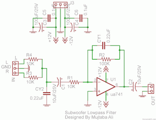
Simple Subwoofer Lowpass Filter using uA741 Single Op Amp Ic

This is the simplest Sub woofer Low Pass filter Circuit using uA741 single op amp ic. The circuit is very low cost with respect to their work. The cut off frequency of this circuit is 25Hz to 80Hz maximum. Using this circuit , you can easily design a 2.1 Sub-woofer Speaker System at your own Home. The circuit contains very few components.In Pakistan, the cost of this circuit with PCB is Rs:45 The same circuit is working in my own hand made sub-woofer system. 

Lowpass Filter using uA741 Single Op-Amp Ic
Parts List: 

R1,R3,R4 = 10K 1/4W
R2=100K 1/4W
CY1,CY2 = 0.22uF Polyester
C1,C2 = 10uF/25V Electrolytic
IC1 = uA741A Single Op-Amp Ic + 8 Pin Ic Socket
3 Pin Male & Female Connector x 2
2 Pin Male & Female Connector x 1
PCB as in required size 4.5 cm x 3.4 cm
See More Detail[...]

Saturday, April 13, 2013

Simple 500W Audio Power Amplifier Circuit Diagram with Transistor

We take transistor MJL2194 and MJL2193 for pressure output signal.so the amp has a capability for enormous instantaneous current potential.

Simple 500W Audio Power Amplifier Circuit Diagram with Transistor

Circuit Functional
I use the -85 volt when the output current is supplied to the drive 350 to 340 very hot. Increase the output present, but it was once too chilly. The output to warmth up sooner than a regular open it. Sounds evident, but sound high quality is somewhat excellent.

I recomment it by way of turning out for the evening. If the force is installed on the steel part out.

I assume simple. View full above, the statement that R 30 ohm then the voltage throughout the 0.86 V exhibit that the brand new via its 29 mA for those who add a file to / – eighty five V, and think that the voltage throughout the part physique. It was the identical in each the R 30 ohm to get an awfully light 5 zero.86 = 5.86 V and the present I can be 5.86/30 = zero.195 A = 195 mA, and the specification of mje340. mje350 get Ic (max) = 500 mA, so it is pure for it to heat up. Actually, it isn't essential to adhere to sync tr output must be interested in the following two tr power force is healthier. For VR will have to be R300 .


See More Detail[...]

Thursday, April 11, 2013

Simple Electronic Lock

There are six (or more) push switches. To unlock you must press all the correct ones at the same time, but not press any of the cancel switches. Pressing just one cancel switch will prevent the circuit unlocking. When the circuit unlocks it actually just turns on an LED for about one second, but it is intended to be adapted to turn on a relay which could be used to switch on another circuit. Please Note: This circuit just turns on an LED for about one second when the correct switches are pressed. It does not actually lock or unlock anything!

Circuit diagram :
 Simple Electronic Lock Circuit Diagram
Simple Electronic Lock Circuit Diagram

Stripboard Layout :

Stripboard Layout
Parts :
  • resistors: 470, 100k ×2, 1M
  • capacitors: 0.1μF, 1μF 16V radial
  • on/off switch
  • push-switch ×6 (or more)
  • stripboard 12 rows × 25 holes
  • red LED
  • 555 timer IC
  • 8-pin DIL socket for IC
  • battery clip for 9V PP3
  •  
A kit for this project is available from RSH Electronics: www.kpsec.freeuk.com


http://streampowers.blogspot.com/2012/06/simple-electronic-lock.html
See More Detail[...]

Wednesday, April 10, 2013

Ultra Simple Microphone Preamplifier

This little project came about as a result of a design job for a client. One of the items needed was a mic preamp, and the project didnt warrant a design such as the P66 preamp, since it is intended for basic PA only. Since mic preamps are needed by people for all manner of projects, this little board may be just whats needed for interfacing a balanced microphone with PC sound cards or other gear. Unlike most of my boards, this one is double-sided. I normally avoid double-sided PCBs for projects because rework by those inexperienced in working with them will almost certainly damage the board beyond repair.

I consider this not to be an issue with this preamp, because it is so simple. It is extremely difficult to make a mistake because of the simplicity. As you can see, the board uses a PCB mounted XLR connector and pot, so is a complete mic preamp, ready to go. Feel free to ignore the terminals marked SW1 (centred between the two electrolytic supply caps), as they are specific to my clients needs and are not useful for most applications. The original use was to use them for a push-button switch that activated an audio switch via a PIC micro-controller. They are not shown on the schematic.

Ultra-Simple Microphone Preamplifier Image Project :
 P12-pic
The DC, GND and output terminals may be hard wired to the board, you may use PCB pins or a 10-way IDC (Insulation Displacement Connector) and ribbon cable. Power can be anything between +/-9V and +/-18V with an NE5532 opamp. The mic input is electronically balanced, and noise is quite low if you use the suggested opamp. Gain range is from about 12dB to 37dB as shown. It can be increased by reducing the value of R6, but this should not be necessary. Because anti-log pots are not available, the gain control is not especially linear, but unfortunately in this respect there is almost no alternative and the same problem occurs with all mic preamps using a similar variable gain control system.

Ultra-Simple Microphone Preamplifier Circuit diagram:

P12-f1

The circuit is quite conventional, and if 1% metal film resistors are used throughout it will have at least 40dB of common mode rejection with worst-case values. The input capacitors give a low frequency rolloff of -3dB at about 104Hz. If better low frequency response is required, these caps may be increased to 4.7uF or 10uF bipolar electrolytics. These will give response to well below 10Hz if you think youll ever need to go that low. The project PCB measures 77 x 24mm, and the mounting centers for the pot and XLR connector are spaced at 57mm. If preferred, a traditional chassis mounted female XLR can be used, and wired to the board with heavy tinned copper wire. The PCB pads for the connector are in the correct order for a female chassis mount socket mounted with the "Push" tab at the top.

source:  http://www.ecircuitslab.com/2011/08/ultra-simple-microphone-preamplifier.html
See More Detail[...]

Simple Electrification Unit

The circuit is intended for carrying out harmless experiments with high-voltage pulses and functions in a similar way as an electrified fence generator. The p.r.f. (pulse repetition frequency) is determined by the time constant of network R1-C3 in the feedback loop of op amp IC1a: with values as specified, it is about 0.5 Hz. The stage following the op amp, IC1b, converts the rectangular signal into narrow pulses. Differentiating network R2-C4, in conjunction with the switching threshold of the Schmitt trigger inputs of IC1b, determines the pulse period, which here is about 1.5 ms. The output of IC1b is linked directly to the gate of thyristor THR1, so that this device is triggered by the pulses.

The requisite high voltage is generated with the aid of a small mains transformer, whose secondary winding is here used as the primary. This winding, in conjunction with C2, forms a resonant circuit. Capacitor C3 is charged to the supply voltage (12 V) via R3.When a pulse output by IC1b triggers the thyristor, the capacitor is discharged via the secondary winding. The energy stored in the capacitor is, however, not lost, but is stored in the magnetic field produced by the transformer when current flows through it. When the capacitor is discharged, the current ceases, whereupon the magnetic field collapses. This induces a counter e.m.f. in the transformer winding which opposes the voltage earlier applied to the transformer.

Circuit diagram:
Simple_Electrification_Unit_Circuit Diagram
Simple Electrification Unit Circuit Diagram

This means that the direction of the current remains the same. However, capacitor C2 is now charged in the opposite sense, so that the potential across it is negative. When the magnetic field of the transformer has returned the stored energy to the capacitor, the direction of the current reverses, and the negatively charged capacitor is discharged via D1 and the secondary winding of the transformer. As soon as the capacitor begins to be discharged, there is no current through the thyristor, which therefore switches off. When C2 is discharged further, diode D1 is reverse-biased, so that the current loop to the transformer is broken, whereupon the capacitor is charged to 12 V again via R3. At the next pulse from IC1b, this process repeats itself.

Since the transformer after each discharge of the capacitor at its primary induces not only a primary, but also a secondary voltage, each triggering of the thyristor causes two closely spaced voltage pulses of opposite polarity. These induced voltages at the secondary, that is, the 230 V, winding, of the transformer are, owing to the higher turns ratio, much higher than those at the primary side and may reach several hundred volts. However, since the energy stored in capacitor C2 is relatively small (the current drain is only about 2 mA), the output voltage cannot harm man or animal. It is sufficient, however, to cause a clearly discernible muscle convulsion.
 
 
Source by : streampowers
See More Detail[...]

Tuesday, April 9, 2013

Simple Cheap LED flasher


This two LED flasher circuit uses any DC supply from 3V to 12V. Flash rate is controlled by R1,C1 and R2,C2. Larger values create slower fash rates, smaller values higher flash rates.
See More Detail[...]

IC LM 386 Datasheet Explained in Simple Words

The IC LM386 is a 8-pin tiny power amplifier chip, specially made for operating under relatively low voltage parameters, yet provide considerable amplification. It becomes suitable for applying in small low power audio gadgets like in FM radios, door bells, telephones etc.


Lets begin the IC LM386 datasheet explanation by studying its absolute maximum ratings first, meaning the parameters which should not be exceeded while using this IC in any circuit:

Supply Voltage: Max. 15V (Typical)

Input Voltage: +/- 0.4 volts

Storage Temperature: -65 degrees to +150degrees Celsius

Operating Temperature:  0 to 70 degrees Celsius

Power Output: 1.25 watts


IC manufactured by: 


How to Control Gain for the IC LM386

In order to make the IC better with its response, its pin#1 and 8 have been attributed with a gain control facility which may be set externally.

Gain simply means the capacity or the amplifying level of the device up to which it is able to amplify the applied input low signal audio input.

When the above pin outs are kept unconnected to anything, the internal 1.35K resistor sets the gain of the IC to 20.

If a capacitor is joined across the above pin outs, the gain is suddenly lifted to 200.

The gain may be simply made adjustable by connecting a pot in series with the above explained capacitor across the pin 1 and 8.

 Practical Amplifier Circuit Diagrams Using the IC LM386

The following figure shows a typical LM386 amplifier circuit having the bare minimum number of components required to make the IC operate at its internally set level of gain 20.
The speaker used is a 2 watt, 8 Ohms type.
The input at Vin may be fed from any audio source such as a cell phone headphone socket, a CD/DVD player RCA L or R socket or any other similar source.

The pin Vs should be connected to +12V DC supply from an AC DC adapter or a home made transformer/bridge power supply unit.

Pin #4 should be connected to ground or the negative of the power supply.

The earth wire or the negative wire from the input audio source should also be connected to the above negative of the power supply.


The input pin#2 goes to a 10K pot which becomes the volume control, one of its end terminals is picked for receiving the input signal while the other end is connected to ground, the center one goes to the hot end of the IC.


The speaker is connected to in #8 via a high value blocking capacitor, the resistor/capacitor arrangement connected across pin #5 and ground has been included for frequency compensation and to provide greater stability to the circuit.

The next circuit shows a similar design as above, except that its pins 1 and 8 have been connected to a capacitor of 10uF, which as explained above helps to pull the gain of the amplifier to 200


See More Detail[...]

Sunday, April 7, 2013

How to Make a Simple Electronic Weighing Scale Machine


Learn a super simple procedure to make a weighing scale device useful for measuring smaller magnitudes of weight. The concept is very simple, a light beam is allowed to pass through a linearly colored ribbon and fall over an LDR. The color shade of the ribbon positioned in front of the light source at any instant will depend on the weight placed over a spring loaded mechanism. The corresponding change in the light level is converted into a corresponding difference in the resistance of the LDR which is ultimately read over an Ohmmeter and the equivalent weight is determined.


A digital weighing scale is an indispensable device as far as determining smaller magnitude of weights is concerned. However these gadgets can be too sophisticated and expensive to procure. A simple design idea of a weighing scale presented here promises to be equally accurate yet very cheap.

Introduction

We all have seen this machine very commonly used with most of the shopkeeper and retailers. It is used for determining the weights of the various materials being sold to the customers so that the items may be correctly rated as per the displayed weight over the machine. This incredible device is able to detect even the minutest magnitude of weight placed over it and accurately displays it over a digital scale.
Yes we are discussing weighing scales normally used for weighing smaller weights ranging from probably mgs up to a few kgs. The commercially available weighing scales are rather too sophisticated, accurate and therefore very costly too.
The design of a simple electronic analogue weighing scale presented here has been devised by me and is pretty accurate, very low cost and can be constructed even by a layman. The idea is simple – a linearly colored semi-transparent ribbon is made to move or dip in response to the pressing weight, a light beam from a light source is allowed to pass through this ribbon and fall over an LDR. The LDR is connected across an Ohm meter, so, as the weight pushes the ribbon, it slides down and settles at a particular point and offers a particular corresponding shade in front of the light source. The light intensity is optimized according to the darkness or lightness of this shade and the LDR reads the proportionate light intensity level and directs it to the meter so that it may be directly read over its calibrated dial.
Let’s try to understand the actual functioning of the designed prototype:


Electrical and Mechanical Description of the Unit
 
 Referring to the figure alongside, we see that the arrangement is pretty straight forward. A central pillar or shaft which forms the main and the sole moving part of the system passes through an appropriately sized hole made over the top surface of the cabinet.
The external end of this rod terminates into a flat platform which forms the base for keeping the weights under question.
The rod and the platform are held in a rigid posture by a spring positioned in between the platform and the cabinet top surface. The shaft actually passes through this spring. The spring is required so that the weights are properly optimized and the level of the platform returns to its original position once the weight is removed.
A linearly colored or darkened translucent ribbon which forms the heart of the entire mechanism is connected to the inner end of the above movable shaft.
Also a white LED (used as a light source) and an LDR (light receiving component) are positioned exactly opposite, facing each other and partitioned by the ribbon.
An analogue moving coil type meter configured as an Ohm meter or a resistance meter is integrated with the LDR.
The LED is powered through a cell and is switched ON when in use. The light beam produced from the LED passes through the ribbon and falls over the LDR and a corresponding value is displayed over the meter depending upon the opacity of the ribbon.
When there’s no weight placed over the platform, the spring mechanism keeps the shaft in a position that produces the darkest shade from the ribbon in the path of the LED beam and therefore the meter also reads a minimum or zero value over its calibration.
The moment a weight on this weighing scale is placed, the shaft dips proportionately and the ribbon slides down to produce a linearly changing shade in front of the LED light beam and finally settles down to a corresponding lighter shade level. The operation is instantly translated over the meter to provide the equivalent value of the weight being measured.


See More Detail[...]

Friday, April 5, 2013

Simple 12V fixed voltage power supply circuit diagram

Here this circuit diagram is for +12V regulated (fixed voltage) DC power supply. These power supply circuit diagram is ideal for an average current requirement of  1Amp. This  circuit is based on IC LM7812. It is a 3-terminal (+ve) voltage regulator IC. It has short circuit  protection , thermal overload protection.  LM7812 IC is from LM78XX series. The LM78XX series IC is  positive voltage regulator IC for different voltage requirements, for example LM7805 IC is made for 5 volt fixed output voltage . There is LM79XX IC series for negative voltage .

Circuit diagram of 12V fixed voltage power supply

 A transformer(Tx=Primary 230 Volt, Secondary 12 Volt , 1Amp step down transformer) is used to covert 230V to 12V from mains. Here used a bridge rectifier made by four  1N4007 or 1N4003 diode to convert AC to DC . The filtering capacitor 1000uF,25V is used to reduce the ripple and  get a smooth DC voltage. This circuit is very easy to build. For good performance input  voltage should be greater than 12Volt in pin-1 of IC LM7812. Use a heat sink to IC LM7812 for safeguarding it  from overheating.

See More Detail[...]