Showing posts with label voltage. Show all posts
Showing posts with label voltage. Show all posts
Tuesday, December 24, 2013
Simple Solar Cell Voltage Regulator Circuit Diagram
This is a Simple Solar Cell Voltage Regulator Circuit Diagram. This device is designed to be a simple, inexpensive ‘comparator’, intended for use in a solar cell power supply setup where a quick ‘too low’ or ‘just right’ voltage indicator is needed. The circuit consists only of one 5V regulator, two transistors, two LEDs, five resistors, two capacitors, and one small battery. Although a 4-V battery is indicated, 4.5 V (3 alkalines in series) or 3.6 V (3 NiCd cells in series) will also work.
Solar Cell Voltage Regulator Circuit Diagram
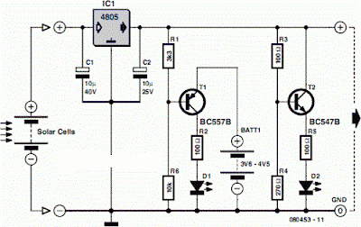
The specifications of voltage regulator IC1 are mainly determined by the size and number of the solar cells and the current pull of the equipment connected to the output. Here the low-drop 4805 is suggested but other regulators may work equally well as long as you observe the output voltage of the solar cells. Transistors T1 and T2 are complementary types i.e. one each of the pnp and npn variety.
Although the ubiquitous BC557B (pnp) and BC547B (npn) are indicated, any small-signal equivalents out of the junk box will probably do. The values of voltage dividers R1/R6 and R3/R4 may need to be adjusted according to the type of transistor and its gain, or according to the desired voltage thresholds. Using the resistor values shown in the schematic, LED D2 turns on fully when the voltage is just above 5 volts.
LED D1 turns on when the voltage drops below 4.2 volts or so. Between those two thresholds, there is a sort of no man’s land where both LEDs are on dimly. A buzzer or other warning device could be connected across the terminals of LED D1 to give a more substantial warning if the voltage drops below operating limits. The current consumption of the circuit is about 20 mA at 5 V, and it decreases with the voltage supplied by the solar cells.

Thursday, August 1, 2013
Battery Powered High voltage Generator Circuit Diagram
This is the battery powered high-voltage generator circuit diagram. Output voltage great enough to jump a l-inch gap can be obtained from a 12-V power source. A 555 timer IC is connected as an stable multi vibrator that produces a narrow negative pulse at pin 3. The pulse turns Ql on for the duration of the time period. The collector of Ql is direct-coupled to tbe base of tbe power transistor Q2, turning it on during the same time period.
The emitter of Q2 is direct -coupled through current limiting resistor R5 to the base of the power transistor. Q3 switches on, producing a minimum resistance between the collector and emitter. The high-current pulse going through tbe primary of high-voltage transformer Tl generates a very high pulse voltage at its secondary output terminal (labeled X). The pulse frequency is determined by tbe values of Rl, R2, and C2. The values given in the parts list were chosen to give the best possible performance when an auto-ignition coil is used for Tl.
Battery Powered High-voltage Generator Circuit Diagram

Friday, April 5, 2013
Simple 12V fixed voltage power supply circuit diagram
Here this circuit diagram is for +12V regulated (fixed voltage) DC power supply. These power supply circuit diagram is ideal for an average current requirement of 1Amp. This circuit is based on IC LM7812. It is a 3-terminal (+ve) voltage regulator IC. It has short circuit protection , thermal overload protection. LM7812 IC is from LM78XX series. The LM78XX series IC is positive voltage regulator IC for different voltage requirements, for example LM7805 IC is made for 5 volt fixed output voltage . There is LM79XX IC series for negative voltage .
Circuit diagram of 12V fixed voltage power supply

A transformer(Tx=Primary 230 Volt, Secondary 12 Volt , 1Amp step down transformer) is used to covert 230V to 12V from mains. Here used a bridge rectifier made by four 1N4007 or 1N4003 diode to convert AC to DC . The filtering capacitor 1000uF,25V is used to reduce the ripple and get a smooth DC voltage. This circuit is very easy to build. For good performance input voltage should be greater than 12Volt in pin-1 of IC LM7812. Use a heat sink to IC LM7812 for safeguarding it from overheating.
Wednesday, April 3, 2013
Automotive Voltage Indicator Monitors battery voltage Three LED Display
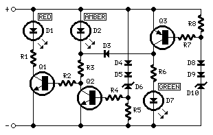
Parts:
R1,R3,R6________1K   1/4W Resistors
R2____________100K   1/4W Resistor
R4,R5,R7,R8_____3K3  1/4W Resistors

D1__________Red LED (Any dimension and shape)
D2________Amber LED (Any dimension and shape)
D3,D4,D5_____1N4148   75V 150mA Diodes
D6_________BZX79C10   10V 500mW Zener Diode
D7________Green LED (Any dimension and shape)
D8,D9________1N4148   75V 150mA Diodes
D10________BZX79C12   12V 500mW Zener Diode

Q1,Q2_________BC547   45V 100mA NPN Transistors
Q3____________BC557   45V 100mA PNP Transistor
Comments:
Connecting this circuit to the battery of your vehicle, you will always know at a glance the approximate voltage available.An
indication of battery voltage is useful to the motorist for
monitoring the batterys capacity to deliver current, and as a check on
the efficiency of the dynamo or alternator.
Threshold voltages of
the LEDs are set by means of two Zener Diodes (D6 & D10) plus two
further Diodes wired in series (D4, D5 and D8, D9 respectively) adding
a step of about 1.3V to the nominal Zener voltage.
LED indication:
- Red LED D1 is on when battery voltage is 11.5V or less. This indicates a low battery charge.
- Amber
LED D2 is on when battery voltage is comprised in the 11.5 - 13.5V
range. This indicates that the battery is good if the motor is off.
When motor is running, this indicates no charge from dynamo or
alternator. - Green LED D7 is on when battery voltage is 13.5V or
more. This indicates a normal condition when motor is running and
dynamo or alternator are charging.
source: redcircuits.com
Subscribe to:
Posts (Atom)