Showing posts with label three. Show all posts
Showing posts with label three. Show all posts
Friday, September 27, 2013
Three Hour Timer
Manufacturers of cordless drills generally recommend a battery charging time of three hours. Once the charging time is up the battery must be disconnected from the charger: if you forget to do this there is a danger of overcharging the battery. This circuit, which sits between the charger circuit and its battery socket, prevents that possibility: the contact of relay Re1 interrupts the charging current when the three hours are up. Ten LEDs show the remaining charging time in steps of 20 minutes. The timer is reset each time power is applied and it is then ready for a new cycle. When power is applied IC3 is reset via C4 and R5. When the charging time has elapsed, Q9 (pin 11) goes high, which turns the relay on and interrupts the charging current.
 Since Q9 is connected to the active-low EN (enable) input, the counter will now remain in this state. The charging time can be adjusted from about 2 hours 15 minutes to 4 hours 30 minutes using P1. The author set P1 to 30 kΩ, giving a charging time of 3 hours 7minutes. The greater the resistance of P1, the shorter the charging time. The timing of the circuit is not particularly precise, but its accuracy is entirely adequate for the job. When adjusting the charging time it is worth noting that the first clock cycle after the circuit is turned on (from Q0 to Q1) is longer than the subsequent ones. This is because initially capacitor C3 has to be charged to around half the supply voltage.
See More Detail[...]
 Since Q9 is connected to the active-low EN (enable) input, the counter will now remain in this state. The charging time can be adjusted from about 2 hours 15 minutes to 4 hours 30 minutes using P1. The author set P1 to 30 kΩ, giving a charging time of 3 hours 7minutes. The greater the resistance of P1, the shorter the charging time. The timing of the circuit is not particularly precise, but its accuracy is entirely adequate for the job. When adjusting the charging time it is worth noting that the first clock cycle after the circuit is turned on (from Q0 to Q1) is longer than the subsequent ones. This is because initially capacitor C3 has to be charged to around half the supply voltage.
Sunday, May 26, 2013
Three sirens in one Circuit
This is a siren circuit diagram Here I have used UM3561 circuit diagram.This circuit can be operated with 3V.It can generate 3 sirens.Here I have used IC 2SC9013 you can use the same IC or similar IC. Use 8ohm 0.2W speaker.
 Note:-
* Dont use more than 3V
* Dont use this for unnecessary things
* Build this circuit on a PCB
See More Detail[...]
Note:-* Dont use more than 3V
* Dont use this for unnecessary things
* Build this circuit on a PCB
Wednesday, April 3, 2013
Automotive Voltage Indicator Monitors battery voltage Three LED Display
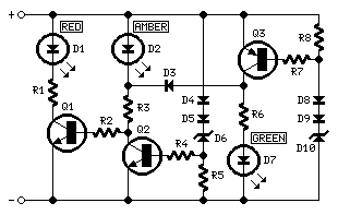
Parts:
R1,R3,R6________1K   1/4W Resistors
R2____________100K   1/4W Resistor
R4,R5,R7,R8_____3K3  1/4W Resistors

D1__________Red LED (Any dimension and shape)
D2________Amber LED (Any dimension and shape)
D3,D4,D5_____1N4148   75V 150mA Diodes
D6_________BZX79C10   10V 500mW Zener Diode
D7________Green LED (Any dimension and shape)
D8,D9________1N4148   75V 150mA Diodes
D10________BZX79C12   12V 500mW Zener Diode

Q1,Q2_________BC547   45V 100mA NPN Transistors
Q3____________BC557   45V 100mA PNP Transistor
Comments:
Connecting this circuit to the battery of your vehicle, you will always know at a glance the approximate voltage available.An
indication of battery voltage is useful to the motorist for
monitoring the batterys capacity to deliver current, and as a check on
the efficiency of the dynamo or alternator.
Threshold voltages of
the LEDs are set by means of two Zener Diodes (D6 & D10) plus two
further Diodes wired in series (D4, D5 and D8, D9 respectively) adding
a step of about 1.3V to the nominal Zener voltage.
LED indication:
- Red LED D1 is on when battery voltage is 11.5V or less. This indicates a low battery charge.
- Amber
LED D2 is on when battery voltage is comprised in the 11.5 - 13.5V
range. This indicates that the battery is good if the motor is off.
When motor is running, this indicates no charge from dynamo or
alternator. - Green LED D7 is on when battery voltage is 13.5V or
more. This indicates a normal condition when motor is running and
dynamo or alternator are charging.
source: redcircuits.com
Subscribe to:
Posts (Atom)