Showing posts with label solar. Show all posts
Showing posts with label solar. Show all posts
Thursday, January 9, 2014
Portable Solar Lamp Lantern
This portable solar lantern circuit uses 6 volt/5 watt solar panels are now widely available. With the help of such a photo-voltaic panel we can construct an economical, simple but efficient and truly portable solar lantern unit. Next important component required is a high power (1watt) white LED module.
When solar panel is well exposed to sunlight, about 9 volt dc available from the panel can be used to recharge a 4.8 volt /600mAh rated Ni-Cd battery pack. Here red LED (D2) functions as a charging process indicator with the help of resistor R1. Resistor R2 regulates the charging current flow to near 150mA.
Solar Lantern Circuit Schematic

Assuming a 4-5 hour sunlit day, the solar panel (150mA current set by the charge controller resistor R2) will pump about 600 – 750 mAh into the battery pack. When power switch S1 is turned on, dc supply from the Ni-Cd battery pack is extended to the white LED (D3). Resistor R3 determines the LED current. Capacitor C1 works as a buffer.
Note: After construction, slightly change the values of R1,R2 and R3 up/down by trial&error method, if necessary.
See More Detail[...]
When solar panel is well exposed to sunlight, about 9 volt dc available from the panel can be used to recharge a 4.8 volt /600mAh rated Ni-Cd battery pack. Here red LED (D2) functions as a charging process indicator with the help of resistor R1. Resistor R2 regulates the charging current flow to near 150mA.
Solar Lantern Circuit Schematic

Assuming a 4-5 hour sunlit day, the solar panel (150mA current set by the charge controller resistor R2) will pump about 600 – 750 mAh into the battery pack. When power switch S1 is turned on, dc supply from the Ni-Cd battery pack is extended to the white LED (D3). Resistor R3 determines the LED current. Capacitor C1 works as a buffer.
Note: After construction, slightly change the values of R1,R2 and R3 up/down by trial&error method, if necessary.
Tuesday, December 24, 2013
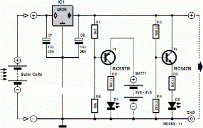
Simple Solar Cell Voltage Regulator Circuit Diagram
This is a Simple Solar Cell Voltage Regulator Circuit Diagram. This device is designed to be a simple, inexpensive ‘comparator’, intended for use in a solar cell power supply setup where a quick ‘too low’ or ‘just right’ voltage indicator is needed. The circuit consists only of one 5V regulator, two transistors, two LEDs, five resistors, two capacitors, and one small battery. Although a 4-V battery is indicated, 4.5 V (3 alkalines in series) or 3.6 V (3 NiCd cells in series) will also work.
Solar Cell Voltage Regulator Circuit Diagram

The specifications of voltage regulator IC1 are mainly determined by the size and number of the solar cells and the current pull of the equipment connected to the output. Here the low-drop 4805 is suggested but other regulators may work equally well as long as you observe the output voltage of the solar cells. Transistors T1 and T2 are complementary types i.e. one each of the pnp and npn variety.
Although the ubiquitous BC557B (pnp) and BC547B (npn) are indicated, any small-signal equivalents out of the junk box will probably do. The values of voltage dividers R1/R6 and R3/R4 may need to be adjusted according to the type of transistor and its gain, or according to the desired voltage thresholds. Using the resistor values shown in the schematic, LED D2 turns on fully when the voltage is just above 5 volts.
LED D1 turns on when the voltage drops below 4.2 volts or so. Between those two thresholds, there is a sort of no man’s land where both LEDs are on dimly. A buzzer or other warning device could be connected across the terminals of LED D1 to give a more substantial warning if the voltage drops below operating limits. The current consumption of the circuit is about 20 mA at 5 V, and it decreases with the voltage supplied by the solar cells.
Subscribe to:
Posts (Atom)