Showing posts with label electronic. Show all posts

Wednesday, October 2, 2013

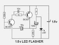
1 5V POWERED LED FLASHER ELECTRONIC DIAGRAM

1.5V POWERED LED FLASHER ELECTRONIC DIAGRAM

It is a charge pump design. This is where a capacitor (electrolytic) is allowed to charge and is then raised higher and allowed to discharge into a load. The load sees a voltage that can be higher than the supply.
See More Detail[...]

Thursday, April 11, 2013

Simple Electronic Lock

There are six (or more) push switches. To unlock you must press all the correct ones at the same time, but not press any of the cancel switches. Pressing just one cancel switch will prevent the circuit unlocking. When the circuit unlocks it actually just turns on an LED for about one second, but it is intended to be adapted to turn on a relay which could be used to switch on another circuit. Please Note: This circuit just turns on an LED for about one second when the correct switches are pressed. It does not actually lock or unlock anything!

Circuit diagram :
 Simple Electronic Lock Circuit Diagram
Simple Electronic Lock Circuit Diagram

Stripboard Layout :

Stripboard Layout
Parts :
  • resistors: 470, 100k ×2, 1M
  • capacitors: 0.1μF, 1μF 16V radial
  • on/off switch
  • push-switch ×6 (or more)
  • stripboard 12 rows × 25 holes
  • red LED
  • 555 timer IC
  • 8-pin DIL socket for IC
  • battery clip for 9V PP3
  •  
A kit for this project is available from RSH Electronics: www.kpsec.freeuk.com


http://streampowers.blogspot.com/2012/06/simple-electronic-lock.html
See More Detail[...]

Sunday, April 7, 2013

How to Make a Simple Electronic Weighing Scale Machine


Learn a super simple procedure to make a weighing scale device useful for measuring smaller magnitudes of weight. The concept is very simple, a light beam is allowed to pass through a linearly colored ribbon and fall over an LDR. The color shade of the ribbon positioned in front of the light source at any instant will depend on the weight placed over a spring loaded mechanism. The corresponding change in the light level is converted into a corresponding difference in the resistance of the LDR which is ultimately read over an Ohmmeter and the equivalent weight is determined.


A digital weighing scale is an indispensable device as far as determining smaller magnitude of weights is concerned. However these gadgets can be too sophisticated and expensive to procure. A simple design idea of a weighing scale presented here promises to be equally accurate yet very cheap.

Introduction

We all have seen this machine very commonly used with most of the shopkeeper and retailers. It is used for determining the weights of the various materials being sold to the customers so that the items may be correctly rated as per the displayed weight over the machine. This incredible device is able to detect even the minutest magnitude of weight placed over it and accurately displays it over a digital scale.
Yes we are discussing weighing scales normally used for weighing smaller weights ranging from probably mgs up to a few kgs. The commercially available weighing scales are rather too sophisticated, accurate and therefore very costly too.
The design of a simple electronic analogue weighing scale presented here has been devised by me and is pretty accurate, very low cost and can be constructed even by a layman. The idea is simple – a linearly colored semi-transparent ribbon is made to move or dip in response to the pressing weight, a light beam from a light source is allowed to pass through this ribbon and fall over an LDR. The LDR is connected across an Ohm meter, so, as the weight pushes the ribbon, it slides down and settles at a particular point and offers a particular corresponding shade in front of the light source. The light intensity is optimized according to the darkness or lightness of this shade and the LDR reads the proportionate light intensity level and directs it to the meter so that it may be directly read over its calibrated dial.
Let’s try to understand the actual functioning of the designed prototype:


Electrical and Mechanical Description of the Unit
 
 Referring to the figure alongside, we see that the arrangement is pretty straight forward. A central pillar or shaft which forms the main and the sole moving part of the system passes through an appropriately sized hole made over the top surface of the cabinet.
The external end of this rod terminates into a flat platform which forms the base for keeping the weights under question.
The rod and the platform are held in a rigid posture by a spring positioned in between the platform and the cabinet top surface. The shaft actually passes through this spring. The spring is required so that the weights are properly optimized and the level of the platform returns to its original position once the weight is removed.
A linearly colored or darkened translucent ribbon which forms the heart of the entire mechanism is connected to the inner end of the above movable shaft.
Also a white LED (used as a light source) and an LDR (light receiving component) are positioned exactly opposite, facing each other and partitioned by the ribbon.
An analogue moving coil type meter configured as an Ohm meter or a resistance meter is integrated with the LDR.
The LED is powered through a cell and is switched ON when in use. The light beam produced from the LED passes through the ribbon and falls over the LDR and a corresponding value is displayed over the meter depending upon the opacity of the ribbon.
When there’s no weight placed over the platform, the spring mechanism keeps the shaft in a position that produces the darkest shade from the ribbon in the path of the LED beam and therefore the meter also reads a minimum or zero value over its calibration.
The moment a weight on this weighing scale is placed, the shaft dips proportionately and the ribbon slides down to produce a linearly changing shade in front of the LED light beam and finally settles down to a corresponding lighter shade level. The operation is instantly translated over the meter to provide the equivalent value of the weight being measured.


See More Detail[...]

Saturday, April 6, 2013

Electronic Touch Switch

Mechanical contacts have the disadvantage that they wear out. That is why it is practical to use an electronic ‘touch switch’ in some situations. With such a touch switch the resistance of the human skin is used for the switching action. The schematic shows the design of a circuit that senses the resistance of the skin and converts it into a useful switching signal. The touch switch contacts can be made from two small metal plates, rivets, nails, etcetera, which are placed close together on a non-conducting surface. In this circuit a comparator of the type LM393 has been used. In the idle state there is, via R1, a voltage equal to the power supply voltage on the non-inverting input of IC1a. Because the inverting input of IC1a is set with R2 and D3 to D5 at the supply voltage minus 1.8 V, the open-collector output of IC1.a is, via R3, equal to the power supply voltage. This voltage is inverted by IC1.b. The voltage at the non-inverting input of IC1.b amounts to half the power supply voltage (through voltage divider R4 and R5) and is lower than the voltage on the inverting input.

Circuit diagram:

electronic-touch-switch-circuit-diagramw

Electronic Touch Switch Circuit Diagram

The output of IC1.b is therefore a ‘0’. If the two touch contacts are bridged with a finger, the voltage at the non-inverting input will become low enough to cause the comparator to toggle state. The moistness of the skin results in a resistance of 1 to 10 MR. If this circuit is used in the vicinity of equipment that’s connected to the mains, then it can be sufficient to touch only the upper contact to operate the switch, provided that the circuit has been earthed. The body then acts as an antenna which receives the 50 Hz (or 60 Hz) from the mains. This is enough to toggle IC1.a at the same 50 Hz. C1/R3 prevent this 50 Hz from reaching the input of IC1b and provide a useable ‘pulse’ of about 10 s at the output of IC1.b. Note that a fly walking across the touch switch conducts enough to generate a switching signal. So do not operate important things with this circuit (such as the heating system or the garage door). Do not make the wires between the touch contacts and the circuit too long to prevent picking up interference. The power supply voltage for the circuit is not very critical. Any regulated DC voltage in the range from 6 to 20 V can be used.

Author: Heino Peters - Copyright: Elektor Electronics Magazine
See More Detail[...]