Saturday, October 5, 2013
Battery Switch With Low Dropout Regulator
 The IC will switch over to the backup battery when it detects that the pass transistor for the main voltage input is in danger of no longer being able to maintain the required output voltage. The device then smoothly switches over to the backup battery. The open-drain status output BACKUP goes low to indicate when this has occurred. When neither battery is able to maintain the output voltage at the desired level the open-drain output DROPOUT goes low. The LT1579 can operate with input voltages of up to +20 V from the batteries. The regulator output OUT is short-circuit proof. The shutdown input switches off the output; if this feature is not required, the input can simply be left open.
Sunday, September 22, 2013
Master Slave Switch

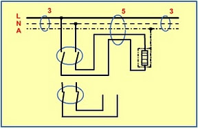
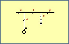
All of the triac drive circuitry (including optical coupling) is integrated on-chip so there are very few external components and no additional power supply necessary. This makes the finished design very compact. Diodes D1, D2, D3 and D4 perform the current sensing function and produce a voltage on C2 when the master equipment is switched on. A Schottky diode is used for D5 to reduce forward voltage losses to a minimum. The circuit is quite sensitive and will successfully switch the slave even when the master equipment draws very little mains current. The RC network formed by R1 and C1 provides some protection for the solid-state relay against mains-borne voltage transients.
Warning:
This circuit is connected to the mains. it is important to be aware that the chip has lethal voltages on its pins and all appropriate safety guidelines must be adhered to! This includes the LED, for safety it must be fitted behind a transparent plexiglass shield.
Wednesday, April 10, 2013
Generator Transfer Switch 300x231 Generator Transfer Switch

Wiring Diagram Of A Generator Transfer Switch Electrical Online.

Generator Transfer Switch Wiring.

Power Transfer Switch.

Generator Transfer Switch 300x231 Generator Transfer Switch.

Generator Set Changeover Switch 250 1600 A Ati Fg Wilson.

Switch 200 Amp Automatic Transfer Switch Service Disconnect.

Generator Transfer Switch 100 Amp 240 Volt Transfer Switches.

Figure 4 Wiring Diagram Of A Manual Transfer Switch In The Off.

Wiring Diagram For Transfer Switch Bst9200m Mts.

Automatic Transfer Switch Installation.
Tuesday, April 9, 2013
AC Mains Bistable Switch

Sunday, April 7, 2013
Dual High Side Switch Controller
Circuit diagram :

Saturday, April 6, 2013
Electronic Touch Switch
Mechanical contacts have the disadvantage that they wear out. That is why it is practical to use an electronic ‘touch switch’ in some situations. With such a touch switch the resistance of the human skin is used for the switching action. The schematic shows the design of a circuit that senses the resistance of the skin and converts it into a useful switching signal. The touch switch contacts can be made from two small metal plates, rivets, nails, etcetera, which are placed close together on a non-conducting surface. In this circuit a comparator of the type LM393 has been used. In the idle state there is, via R1, a voltage equal to the power supply voltage on the non-inverting input of IC1a. Because the inverting input of IC1a is set with R2 and D3 to D5 at the supply voltage minus 1.8 V, the open-collector output of IC1.a is, via R3, equal to the power supply voltage. This voltage is inverted by IC1.b. The voltage at the non-inverting input of IC1.b amounts to half the power supply voltage (through voltage divider R4 and R5) and is lower than the voltage on the inverting input.
Circuit diagram:

Electronic Touch Switch Circuit Diagram
The output of IC1.b is therefore a ‘0’. If the two touch contacts are bridged with a finger, the voltage at the non-inverting input will become low enough to cause the comparator to toggle state. The moistness of the skin results in a resistance of 1 to 10 MR. If this circuit is used in the vicinity of equipment that’s connected to the mains, then it can be sufficient to touch only the upper contact to operate the switch, provided that the circuit has been earthed. The body then acts as an antenna which receives the 50 Hz (or 60 Hz) from the mains. This is enough to toggle IC1.a at the same 50 Hz. C1/R3 prevent this 50 Hz from reaching the input of IC1b and provide a useable ‘pulse’ of about 10 s at the output of IC1.b. Note that a fly walking across the touch switch conducts enough to generate a switching signal. So do not operate important things with this circuit (such as the heating system or the garage door). Do not make the wires between the touch contacts and the circuit too long to prevent picking up interference. The power supply voltage for the circuit is not very critical. Any regulated DC voltage in the range from 6 to 20 V can be used.
Author: Heino Peters - Copyright: Elektor Electronics Magazine
Thursday, April 4, 2013
Double Pole Switch Installation